Showing posts with label AUSTRAINS. Show all posts

Tuesday, 28 May 2019

30 Class Tank Lighted

The Auscision 30 Class is also supplied in a lighted version and is tighter that the non lighted model blogged previously.tank has no real space for a sound decoder and thus has to be installed in the cab area. This conversion dose require use of small hand tools to complete the necessary modifications


Begin by removing the cab roof, this is clipped in at the front and rear and can be removed 
using a small blade screw driver, next separate the bunker extension located on the top of the coal bunker, these are mounted by a small moulded lug into the all metal coal bunker. 

To remove the coal bunker locate the two screws securing the bunker on the underside of the footplate, these are be removed with a small Phillips head screwdriver. Do not remove the screws under the side bunker

See photos for clarity, place the screws and bunker to one side.


With the parts separated modify the cab rear and bunker extension as shown below. A fine razor saw and file are required to complete this task. Remove the glazing before modifying the cab then mark the glazing from the cab and modify as required then reinstall with a small dot of contact cement.


CAB MODIFICATION - numbers are in mm
Note clips that secure the cab


BUNKER EXTENSION MODIFICATION - numbers are in mm

The decoder loom is to long and we chose reduced the overall length to 30 mm - speaker wire should be 35 mm. 


Note: The MRRC will modify this with a charge at time of ordering. The location of the #1 pin [Orange wire] means that when soldering the wires to the plug that this be accommodated - see diagram opposite.

This is required to allow plug to be installed into the socket


The installation of the SoundTraxx Econami UK creates a number of issues over a ESU in that a capacitor is required and requires a edge port speaker to prevent crowding the cab area. The speaker used has a 6 ohm impedance and if the master volume and in particular the whistle a kept at about 2/3 maximum volume this will be OK.

The capacitor was fixed in the mouth of the firebox door and painted black after marking the negative [grey stripe] clearly. Glue with a dot of contact on the base ,set aside to dry.


Comment
Refer to blog on installing a ESU decoder into a non lighted 30 Class for additional information

Wednesday, 5 September 2018

80 Class

The 80 class requires planning and we recommend reading these instructions , identify all the parts before proceeding.

To install your sound decoder in the Austrians 80 class you will have to first remove the body, this simply clips to the chassis. Remove the four screws retaining the body weight and the existing lights and associated wiring, place to one side we will reuse the lights not the diodes.

Drill a 5 mm hole thru the weight at such a angle as to intersect the under side of the tongue, refer photo opposite. Do this in a drill press with a suitable vice as you must exercise care to get the correct angle.


5 mm Hole drilled

This hole is drilled at the end of the locomotive and is at the opposite to the recess in the frame shown in the next photograph.

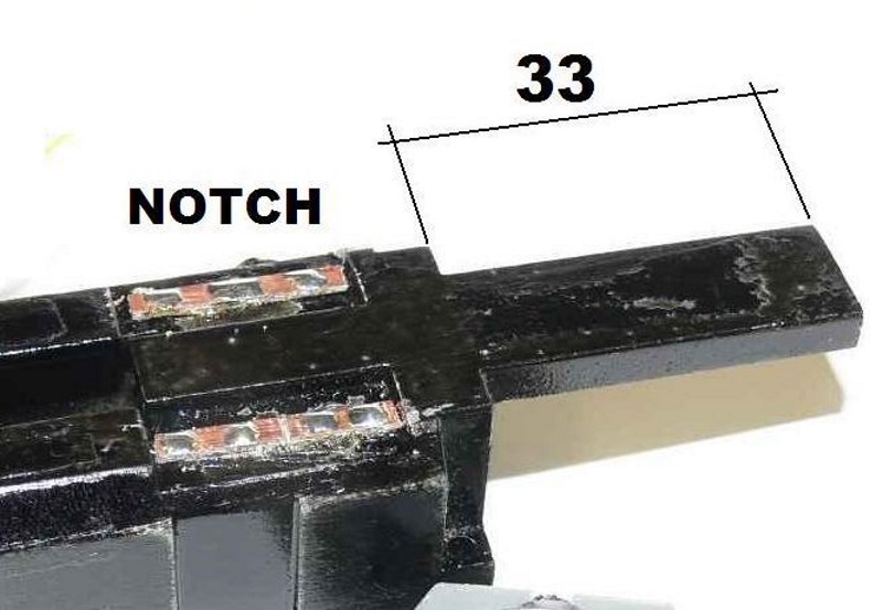
Locate the end with the two notches and this will be the front of the engine. Cut the light mounting down to a length of 33 mm [50 mm as supplied] using a saw, ensue the cut is as square as possible, dress with file if required.


The decoder MUST be mounted at the rear of the locomotive so make sure you drill and CUT the right ends, refer location of the notch this is the front of the engine weight.

Note Optional:
Fit two pieces of PCB, trim to size and glue into the position shown in the photo, this is in the recess in the weight.Select one and tin at three points, next cut thru the top layer of the PCB about its centre line, this forms two separate solder pads, apply two points of solder on each pad, these will be used later to collect up the lights

Drill a 1.5 mm hole thru the top feed wires thru and test fit speaker and thread wires thru 1.5 mm hole.Test fit the speaker to the casting, clean any moulding imperfections with a single edge modellers blade using a scraping action. Urethane is very soft and will remove quickly so exercise a little patience.

Apply a thin a bead of sealant refer area A into the recess and then fit speaker. Next seal opening were the wires exit and the notch in the base at point C, set aside and allow to dry. The base may need a sand to remove the taper created in the casting process, work slowly with a guide utill flat.


Mount Decoder on underside of rear tongue and
thread wires through as shown

Remove the wire soldered to the slip on the metal clip on the topside of the motor as we will not need this. The lower side of the motor has two wires connected to the motor, we cut one of the [blue wire in photo] flush with the point is fixed to the motor. Next we connect the front and rear trucks with a new feeder in black and red. Red is on the right hand side looking from the rear of the locomotive forward. 


Decoder mounting


Finally place a solder point on the top side of the metal strip located on the topside of the motor.

Next install the decoder, cut off the NMRA 8 pin plug and thread the wires thru the hole we drilled in the chassis. 

Cover the mounting face with a layer of electrical tape and then install the decoder on its flattest face threading the wire thru the hole provided, fix decoder with a loop of electrical tape as shown in the photo's opposite.

Now begin to connect the decoder onto the solder points provided on our modified frame. Loop the red and black decoder wires to their respective trucks [refer photo's]. Thread the wire from the bottom motor connection thru slot on frame.

Connect the motor, solder the grey lead to the solder point on the strip located on the top of the motor, connect he orange wire from the decoder to the wire from the bottom of the motor, solder together, insulate with liquid insulation or heat shrink.

The light connections are now added, blue to the common copper strip with the three points of solder and the yellow and white to one of the split pads.


The lights will consist of two lights, trim to length and solder one leg to the solder point on the common blue decoder wire solder pad and the other to the split pad, one pad is used for the white decoder wire for the front headlight and the other for the yellow decoder wire for the rear headlight. 

Cover the lights with a length of black electrical tape to seal the lights at both ends [front shown without cover for clarity]

Insulate the bare connections and using a electrical tape tidy up all the wires recheck connections and you are ready to program the decoder.


Crew points are provided but they will require cutting along the body line to fit the recess provided but this is not noticed from the outside.

One you are sure everything is running refit body and you are ready for the track.

Note: you will not hear the decoder fully until the body is installed.

Wednesday, 4 July 2018

41 Class Stay Alive


This blog covers the installation of a stay alive in a Austrains 41 Class

The ESU say alive is the only commercial product that will fit this engine and requires modification to the hoot to be installed. 

Note: ESU stay alive's only work with a ESU decoder.

It is the easiest to do this with the hood removed. 

To do this remove the handrails installed into the cab sides with a set of small pliers. It is best to leave the factory foam that supports the handrail for this whole process.

The cab  body is secured by six [6] clips - break the lugs that engage the hood as it is impossible to release all of them at the same time. Using a screwdriver disengage the lugs in the running board by pushing along the board then down - not easy.

With the four [4] lugs push / pull the cab off - it is tight so care mixed with force is required. Once removed dress the side of the cab where it rubs in the hood to open up the clearance a little - a few wipes with a flat jewellers file will do the job.

Enlarge the slot in the hood to take the stay alive as shown

Note: Remove the capacitor from the board taking note of which side the negative is marked by the stripe on the side of the capacitor, this is the negative side.

Solder a red and black wire to the capacitor to keep track of the positive / negative and reinstall on the board - tape to the engine on the opposite side to the decoder

Test and reassemble.

Sunday, 1 July 2018

41 Class Diesel

AUSTRAINS 41 Class

Remove loco from its packaging. On both ends of the loco, you will see the smoke stacks (4 in total). Carefully remove these from the body by gently pulling them vertically off. They have small pins at the bottom which engage into the body- be careful not to bend the pipes otherwise they may break. 


As they stick up above the roof line and may be damaged during the removal of the body.


Easily lost - use 0.012' CMA wire to replace

Using a pair of tweezers, you now need to remove the coupler release bar from the coupler boxes. There is one at each end. Carefully lift the bar out of the bottom of the coupler box, and remove the other end from the frame. Once this is done, unscrew the screw holding the coupler and coupler box and remove.


Beside the fuel tank, on opposite corners, you will find two screws. These need to be removed. Once this is done carefully lift the body off the frame. It should lift straight off. Do not pull the frame by the fuel tank. 

Remove the body and set aside. 

You will find at one end of the loco the 8-pin DC plug remove to begin install.


Using a soldering iron with a small tip you need to unsolder the two speaker wires from the speaker pads beside the 8-Pin plug (shown by the arrow). Then, solder these two wires to the two Brown wires from the sound decoder. Wrap these solder joints in tape to protect them or use some fine heat shrink tube.


Using a Loksound Select, fit the decoder to the loco. NOTE: The Orange Wire/Pin is Pin 1 and the decoder should be plugged in so the Orange Wire/Pin is in the socket where the arrow is (shown by the arrow above).

Note: The 8-Pin plug from the decoder is facing the wrong way in the picture. Make sure the Orange wire corresponds with the arrow pin (shown in the photo on the previous page).

Make sure all wires are taped down and not loose. Also check the black and red wires on the loco they have guide holes in the PCB board where they run through, make sure they are still sitting in these guides. 

See the attached photo to double check, failure to do this may damage the wires when you try to put the body back on.


TEST RUN THE LOCOMOTIVE AND SET ADDRESS USING 
PROGRAM ON MAIN

Re-fit the locomotive body and screw the body to the frame with the two screws on the diagonal of the fuel tank. 

Re-fit the couplers and boxes, as well as the coupler release bar

Re-attach the smoke stacks to the body top

With a Loksound you will also need to press F8 to engage the prime mover sounds.

With thanks to Ben Small.

Wednesday, 27 June 2018

30 Class Tank

The Auscision 30 Class tank has no real space for a sound decoder and thus has to be installed in the cab area. This conversion dose require use of small hand tools to complete the necessary modifications


Begin by removing the cab roof, this is clipped in at the front and rear and can be removed using a small blade screw driver to undo the screws holding the coal bunker. To remove the coal bunker locate the two screws securing the bunker on the underside of the footplate, Separate the bunker extension located on the top of the coal bunker and then the cab and could bunker.

Note: The cab has 4 lugs and these may have to be leaver out with a small screwdriver

See photos for clarity, place the screws and bunker to one side.

With the parts separated modify the cab rear and bunker extension as shown below. A fine razor saw and file are required to complete this task. Remove the glazing before modifying the cab then mark the glazing from the cab and modify as required then reinstall with a small dot of contact cement.


CAB MODIFICATION - numbers are in mm
Note clips that secure the cab


BUNKER EXTENSION MODIFICATION - numbers are in mm

The decoder loom is to long and we chose reduced the overall length to 25 mm - speaker wire should be 30 mm. 

Note: The MRRC will modify this with you order for a small charge at time of ordering.

Seal the MRRC Micro Boost speaker by removing the moving coil pack from the supplied enclosure then applying PVA / Craft glue around the rim with a tooth pick or similar. Reinsert the speaker and allow to dry for 20 minutes. Glue the speaker onto the cab floor using some contact cement an allow to dry.

Blacken the enclosure using a Sharpie then the side of the decoder to help it hide in the cab before installation.


Ready for final assembly

Solder the speaker wires onto the speaker tap - set the iron to 270 deg C for this task.

Thread the loom through the bunker and plug into the factory board as shown then rest the opposite end of the decoder onto the top side of the back head. The speaker wires were tied up with a loop of black electrical tape - get the good stuff, Nitto if you can.


TEST RUN THE LOCOMOTIVE ON ITS DEFAULT ADDRESS OF 3


Add a crew from Kerroby Models and the hardware will not be visible

Clip the cab back in by engaging the front lugs and while pushing forward against them push down carefully to engage the rear lugs. 

Install the bunker extension by re-engaging the pins into the coal bunker - if damaged a wipe of contact will secure the frame to the coal bunker.

This should work with the lighted engine also.

Comment
Refer to blog on installing a Soundtraxx decoder into a lighted 30 Class for additional  information