Thursday 23 November 2023

Powerline T Class

This blog cover the installation of sound into the Powerline T class and a SoundTraxx Econami - intermediate level

The shell is secured using four [4] self tapping screws located on the underside of the locomotive at each end. These are very short and may not grip on reinstallation, so be careful when tightening. Next, remove both coupler and pockets. We recommend the couplers be replaced, they are a low quality copy of the Kadee, whisker type recommended.

The board used is a standard Atlas DA-SR type and secured with the clips inserted through the decoder. Photo graph all the wiring before proceeding.

Both the markers are wired to the front and rear headlights alternatively and we will split these at installation. The wiring colours are all over the place so just identify each one removed which is done by sliding back the plastic clips and removing the wire. Once done arrange so you know who is who especially the track pickups.

Extend the motor wires by about 30 mm for reinstallation.

Locate the front of the decoder as per the diagram supplied with the decoder after tinning all the front and rear lugs along with the speakers and FX3/4.

Remove the mounting clip using the two screws into the chassis and relocate so the wire retainers are just over the rear edge of the current mounting location. Secure using ACC or Kaptron tape.


Mounting clip and speaker refitted


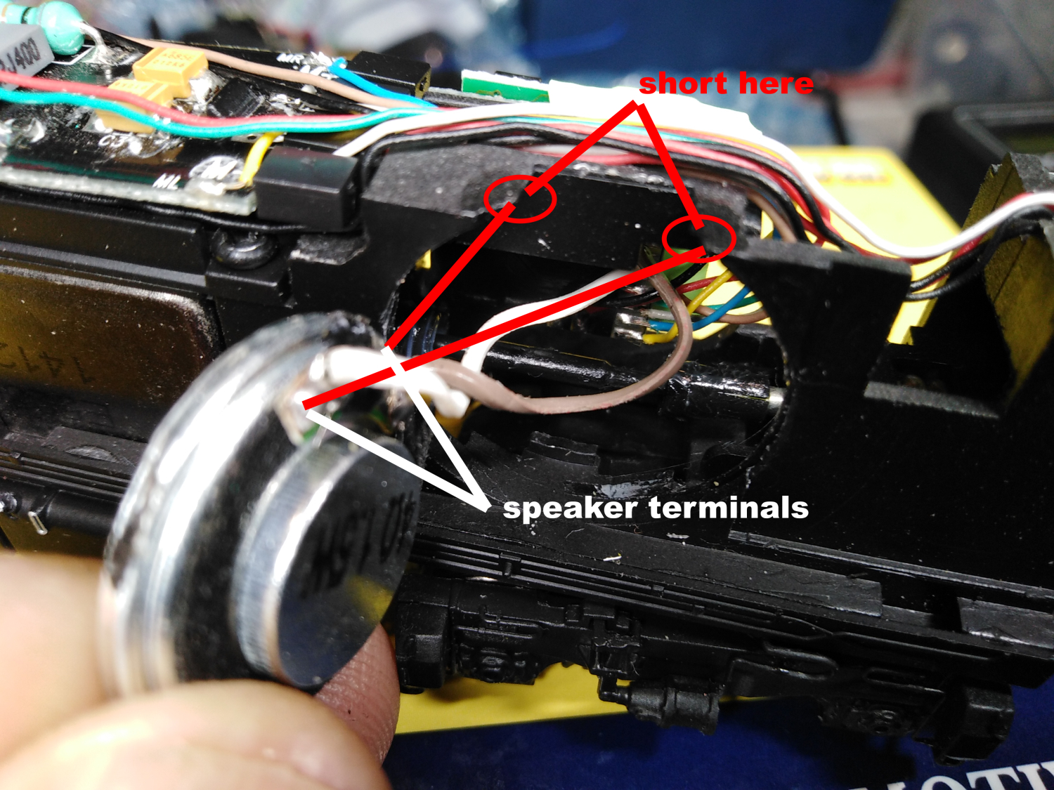
Next solder the speakers wires onto the speaker allowing about 60 mm for trimming at installation. Secure the speaker in its location in the pocket at the rear of the chassis near the rear lighting.

Buzz the track wire to confirm which ones are the track wires, there are NO mistakes here.

Solder all the wires to there respective lugs including the front and rear markers FX3/4 - Front/ Rear markers. Note how on the rear wiring the unused mounting holes are used to keep the wires in place for reassembly


Check you have 8 ohms across the speaker attachment points after soldering the wires.

Place your locomotive and connect the PowerCab to one track after setting it to display to amps. Tap the other wire on the track and if the current runs past 0.04 amps STOP there is something wrong. 

With the Soundtraxx Econami decoder shown a blue status light will shown that all is OK. Configure the decoder to your personal taste, we used JMRI as most sound decoders are well beyond hand programming.

Test is all is OK reinstall the shell in the reverse order. We found it harder to install than remove and dressed both end to remove every burr and finally it slipped back but I cannot confirm why.

With tuning it will run smoothy but mak

Ensure the wheels are polished as this locomotive could do with a small stay alive but there is barely any room for the speaker as it is. We polish the wheels by liberally applying WD40 to the track and wheels and allow the loco to run at speed step 3-4 against a fixed stop across the track. When done thoroughly clean the wheels with WD40 using a cotton bud.


Wednesday 19 April 2023

NCE Dual Relays

NCE produced the Dual relay to allow both the Switch-it and the Switch 8 to operate as a digital switch using the Dual relay.

The reason is solid-state transistor switch on the decoders can only handle about 40 ma, which is more than enough for a typical; Tortoise motor but is limited to that. The Dual Relay was created to handle up to 2 amps to allow the decoder to switch a relay. To achieve this, the relay coils had to have high resistance to limit the current within both decoder specifications.

There is an error in the nomenclature printed on the decoders. It's all back to front, and if wired as shown, it will not operate, or the wrong outputs will operate.

I have created a correct corrected image that will operate as specified when wired as shown will operate to specification..


Wednesday 1 March 2023

Bendigo Models T Class

The ESU V5 sound decoders cannot have the audio shorted at any point when power from the track is applied. Most of the files we supply are tidied-up files from ESU and are tested before dispatch, that is, they are run in a decoder tester with a large speaker, so we know they work at dispatch.

A customer returned this locomotive with the decoder and speaker installed, as we could not diagnose the issue over the phone. The customer retested the locomotive with the DC plug, which ruled out a locomotive issue as the engine ran smoothly.


When tested in the ESU programmer, the decoder returned
"Decoder not recognized" regardless of the method applied. We then realised that the speaker had been installed in reverse, which shorted the speaker terminals across the chassis at the top edge.


As shown, the speaker mount was designed to have the speaker face into the chassis; a final trick to get the best volume is to apply a piece of brown packaging tape across the back before reinstallation. This seals the enclosure in a superior manner to the locomotive wall and will increase speaker fidelity in operation.


I chose to seal the gap between the rim of the speaker and the frame using liquid insulation available at Jaycar. It is expensive and prone to drying up, so as you use it, wind up the used portion of the tube at all times, fit the cap and store it nose down. Now does it make a great difference, hard to say, but it will cannot hurt.

Note: The ESU 23 mm 4-ohm speaker is the only one that will fit this application. Our micro-speaker is a good substitute if not available.

As the engine and decoder were supplied by the MRRC, this cost $75 for a new decoder repair and installation.


Correct installation and remember the packaging tape
across the back of the speaker


Saturday 21 January 2023

NMRA 8 pin plugs

This is a small warning about using the DC shorting strips supplied with any DCC-comparable engine.

These are NOT an 8-pin plug as they have shorting strips connecting the motor and lights directly to the track, and if used without removing ALL these connections, it will destroy your decoder.


An 8-pin plug is just that, 8-pins with NO connections. I strip all the wires on the decoder about 4 mm, and then all the wires are tinned with the iron tip at about 325 deg C to reduce the pullback of the PVC insulation.

Apply a small amount of solder onto the tip, then touch the tip to the wire end, and finally touch the 60-40 resin solder, allowing the solder to flow up the bare wire. Finally, trim the soldered end to about 1 to 1.5 mm.

Fit the plug into any 8-pin socket, I use my decoder tester for this task. This prevents the plug from damaging itself when the wires are added. If it is, an 8-pin IC socket fill the holes with solder before attempting to attach any wires. A PCB wire type has a pool of solder as part of its assembly.

Start with the orange, complete the lower and then the upper row. Check against the diagram the check again...!

NMRA 8 pin wiring pattern