Wednesday 12 December 2018

Lima XPT

Thought these are now getting old the XPT is still popular as it offers a cheap Australian look alike.

Installation
It was decided to install a Lasic decoder with stay alive as they are a good cost match to the locomotive. The installation is straightforward as the motor pickup is clearly located on the motor.

Begin by removing all the existing wiring for the motor and lights as these will be upgraded to LED as part of this conversion.

DCC is very sensitive to pick-up and the basic pickup originally supplied with these locomotives has to be improved, this is done in two ways, firstly the front bogie is rewired and upgraded and secondly a stay alive was added.


Fixing locomotive weight

Modification to front bogie consist of hardwiring to the factory pickup

Lower clip is released and the working face cleaned and tinned, a feeder wire was soldered  and a hole drilled to allow it to pass through the bogie frame 

Note: ensure that the exit point does not foul on the pickup of the assembly

A hole is drilled through the frame to allow connection to the tab, next the tab was fixed over the pin by pushing it over the pin and then lifting the pin to engage in a groove located on the pin.

Decoder installation - the grey & orange arranged as shown allowed
fwd to operate correctly

Decoder and Stay Alive Installation

In the image above note the heat shrink, this contains a pin/socket that allows the stay alive to be disconnected for programming - this proved to be an issue with this decoder.


LED headlight

A LED installed replacing the rather clunky headlight original installed. To do this the cover was removed from the chassis and a LED module incorporating the LED and resistors, it was fixed with contact cement to the locomotive cover and once dry the refitted to the chassis.


Cutout to clear decoder

At assembly, the perspex fouled the decoder but a quick trim allowed a neat fit and finally the hood to be reinstalled.

With a small amount of adjustment and clean wheels, it moved off with as much grace as these units are capable of.

All items used in the installation are available from the MRRC.

Wednesday 5 December 2018

21 pin Stay Alive

This blog covers wiring a stay alive to a 21 pin TCS decoder but is applicable to all decoder conforming to the 21 pin standard

TCS do not recommend soldering onto the decoder

Using the attached image solder the black [earth pin 20] and blue [positive pin 16] onto the pin of the adaptor board. When finished ensure that no balls or solder bridges are present as the SD card slot resets are close to these pins.

If the 12 volt comes into compact with the blue pin comes into contact with the SD card slot will send 12V to ground and will cause arcing/sparking that will destroy the decoder.

Use of Kapton tape across the pads is recommended.

Note: Do not use additional KeepAlive devices in parallel with the TCS motherboard.


ESU provide a basic adaptor board for this installation - click here

Wednesday 26 September 2018

Setting Long Address

The QSI decoders installed in typicialy in the Eureka range and have a voice readback as do all QSI decoders, this can cause issues when setting a long address.

To set a long adress the voice read back must be turned off.

Puct you locomotive on the track and select, loco, 3 do not put any zeros in front as it will be long 3 and this is a different address - OK.

Next blow the whistle to confirm that you are communicating with that engine successfully.

Next use PROM [programing on the main] and get to the screen on a NCE system that shows

1 - ADR  2 = CV 

Select 2, enter

CV number = 62 , enter

CV value = 0 , enter

Return to the original screen

1 = ADR

Select long address and enter the locomotive number.

To turn voice readback on repeat the process above except set CV 62 to a value of 1. Generally we leave it off

Hope this helps and remember 90% of problems with QSI decoders are fixed with a reset

Frateschi Replica NR

The can be described as basic install but is a good example of converting older engines to DCC with a simple non sound decoder.


The locomotive shell simply slips off exposing the factory board and LED lights - there is no DCC plug.

Begin by removing the board by cutting the front and rear bogie connections and the motor connections, remove the board as it is replaced with a DCC decoder. The selected decoder is a NCE Bach DSL but a DA-SR is a good alternative for other locomotives. A NCE Bach DSL was chosen because it placed the lights in the same location as the factory board and was in fact a similar size.


As there are no mounts the board was secured using two [2] beads of silicon along the top side of the motor then the board fitted and aligned and then set aside to dry for 24 hours.

The final job was to connect the track pickups and the motor wires, test run to confirm direction.

Note: if direction is incorrect at this time simply swap motor wires

Test run and adjust the motor settings. On this locomotive CV116 kick was set to 2 and CV117 kick strength was set to 25 resulting in the locomotive moving off smoothly at about speed step 2.

When happy, refit shell - done.

NR92

The Austrains NR92 is a good first sound install because of Auscision decision to screw the shell and a generally a tidy fit.

The engine file is a 7FLD-16 - Decoder ESU

Begin by removing the couplers from both ends noting the rear coupler with have a air hose that is bet removed and placed in the lid until reassembly. With the couplers out remove the two [2] screws located near at both ends. Place to once side with the couplers.


Next pull the lid off carefully starting at the rear moving to the front. You will find the front a tougher but it will rock off and then place beside the mechanism.

Note: Be careful here as the headlights are plugged into the main PCB and the lead are quite short and if damaged cannot be repaired

Mark one ot the plugs with a Sharpie so you can reassemble in the correct order. Remove the both plugs with a small chisel screwdriver and place body to once side


Next remove the factory DC 21 pin jumper and then install the 21 pin decoder.

Note: Pins are inserted through the the PCB board.

Solder two lengths of wire to the speaker then to the two speaker connections on the factory PCB. Install the speaker into the factory speaker enclosure threading the wires through the front slot, seal this opening with a dob of silicon and allow to dry.

Solder the speaker wires to the two speaker points on the factory PCB. Thread the wires in between the gap between the speaker enclosure and the frame on both sides. Once fitted cover with a piece of electrical tape to allow the shell to fit over. 


Test the lights and the sound then refit the plugs to connect the headlights in the shell and retest the lights.

Once satisfied refit the shell from the rear and then over the speaker - this will be a little tight but will fit.

Reinstall mounting screws then the couplers, finally refit the air hose with a drop of ACC.

Retest and set adress  

Wednesday 5 September 2018

80 Class

The 80 class requires planning and we recommend reading these instructions , identify all the parts before proceeding.

To install your sound decoder in the Austrians 80 class you will have to first remove the body, this simply clips to the chassis. Remove the four screws retaining the body weight and the existing lights and associated wiring, place to one side we will reuse the lights not the diodes.

Drill a 5 mm hole thru the weight at such a angle as to intersect the under side of the tongue, refer photo opposite. Do this in a drill press with a suitable vice as you must exercise care to get the correct angle.


5 mm Hole drilled

This hole is drilled at the end of the locomotive and is at the opposite to the recess in the frame shown in the next photograph.

Locate the end with the two notches and this will be the front of the engine. Cut the light mounting down to a length of 33 mm [50 mm as supplied] using a saw, ensue the cut is as square as possible, dress with file if required.


The decoder MUST be mounted at the rear of the locomotive so make sure you drill and CUT the right ends, refer location of the notch this is the front of the engine weight.

Note Optional:
Fit two pieces of PCB, trim to size and glue into the position shown in the photo, this is in the recess in the weight.Select one and tin at three points, next cut thru the top layer of the PCB about its centre line, this forms two separate solder pads, apply two points of solder on each pad, these will be used later to collect up the lights

Drill a 1.5 mm hole thru the top feed wires thru and test fit speaker and thread wires thru 1.5 mm hole.Test fit the speaker to the casting, clean any moulding imperfections with a single edge modellers blade using a scraping action. Urethane is very soft and will remove quickly so exercise a little patience.

Apply a thin a bead of sealant refer area A into the recess and then fit speaker. Next seal opening were the wires exit and the notch in the base at point C, set aside and allow to dry. The base may need a sand to remove the taper created in the casting process, work slowly with a guide utill flat.


Mount Decoder on underside of rear tongue and
thread wires through as shown

Remove the wire soldered to the slip on the metal clip on the topside of the motor as we will not need this. The lower side of the motor has two wires connected to the motor, we cut one of the [blue wire in photo] flush with the point is fixed to the motor. Next we connect the front and rear trucks with a new feeder in black and red. Red is on the right hand side looking from the rear of the locomotive forward. 


Decoder mounting


Finally place a solder point on the top side of the metal strip located on the topside of the motor.

Next install the decoder, cut off the NMRA 8 pin plug and thread the wires thru the hole we drilled in the chassis. 

Cover the mounting face with a layer of electrical tape and then install the decoder on its flattest face threading the wire thru the hole provided, fix decoder with a loop of electrical tape as shown in the photo's opposite.

Now begin to connect the decoder onto the solder points provided on our modified frame. Loop the red and black decoder wires to their respective trucks [refer photo's]. Thread the wire from the bottom motor connection thru slot on frame.

Connect the motor, solder the grey lead to the solder point on the strip located on the top of the motor, connect he orange wire from the decoder to the wire from the bottom of the motor, solder together, insulate with liquid insulation or heat shrink.

The light connections are now added, blue to the common copper strip with the three points of solder and the yellow and white to one of the split pads.


The lights will consist of two lights, trim to length and solder one leg to the solder point on the common blue decoder wire solder pad and the other to the split pad, one pad is used for the white decoder wire for the front headlight and the other for the yellow decoder wire for the rear headlight. 

Cover the lights with a length of black electrical tape to seal the lights at both ends [front shown without cover for clarity]

Insulate the bare connections and using a electrical tape tidy up all the wires recheck connections and you are ready to program the decoder.


Crew points are provided but they will require cutting along the body line to fit the recess provided but this is not noticed from the outside.

One you are sure everything is running refit body and you are ready for the track.

Note: you will not hear the decoder fully until the body is installed.

Tuesday 28 August 2018

Octo 3 LED's

Tam Valley offer the own point selector with push buttons and LED indicators but what if you want to use your own dedicated panel.


TAM Notes:


The S pin goes high and low to five LEDs.  The middle pin is +5V and the B pin is ground.  You can use these to drive LEDs.

Here is the typical circuit, one LED will be lit at a time.

30T Class

The Wombat 30T is supplied with a small 6 wheel tender making sound installation a more difficult issue and this blog covers the installation of a Soundtraxx Econami UK decoder

The tender is secured with a series of molded clips on the floor that hold the body , remove shell using a fine blade or blade screwdriver. Exhibit care as the rear markers are secured to the tender back with a loom and plug.

With the shell removed unplug the markers at this point of the install - Place the tender to one side remembering there are some fine details attached to the coal bunker sides.

Tender shell removed

The first modification is to remove the factory plastic speaker base - this is mounted with small self tappers - remove and discard as it is not required. Its removal creates the room to allow reuse of the factory plug assembly and locomotive loom.

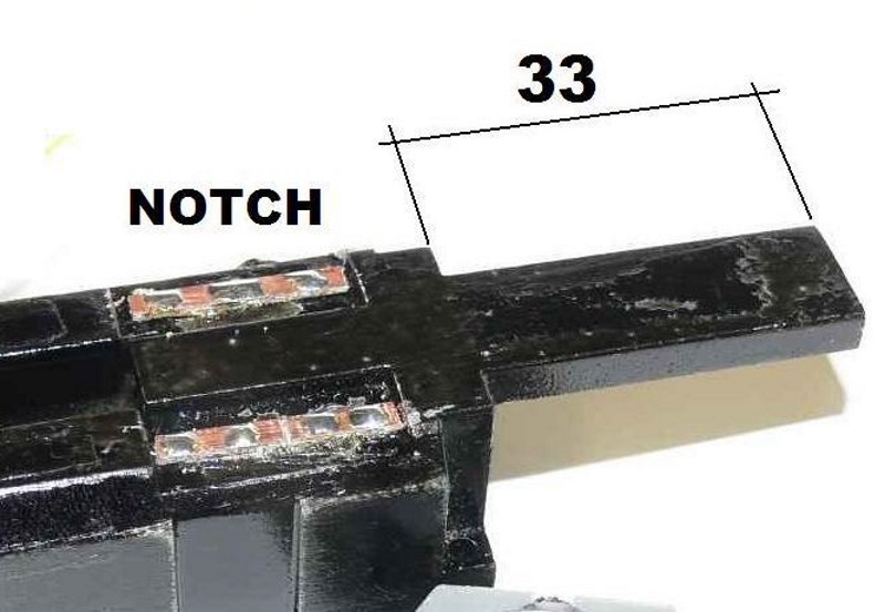
A piece of business card is cut to 34 x 14 mm and glued to the deck just to be sure, once this is done the original PCB is trimmed on the underside with a set of Xurons to remove as many of the spikes as possible and fixed to the cardboard with contact cement.


34 x 14 Insulator

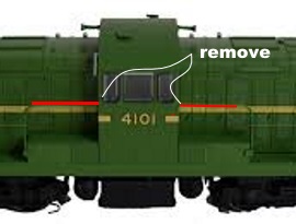
Next we remove the two [2] factory switches - Note where the black wire from the switch is terminated - mark this and then remove the wire from the switch then solder the lead to the board bypassing the switch.

You can chose to do the same for the rear markers and these will be then on the headlight in reverse when the decoder is configured however we chose to allow independent control.

To do this remove both switches and the wire to the pad / decoder. 


Remove switches

Cut the overall length of the wires supplied to about 35 mm and solder to a 8 pin NMRA plug to the diagram opposite - there is not enough room for a full loom.


Solder the capacitor to the manufacturers detail. Connect the green/yellow to the negative and then using the surplus blue wire solder this to the blue on the plug and to the positive of the capacitor. 

Next split the wire and solder the positive [red] wire into the blue.

The brown wire for FX4 is connected to the black wire of the marker with a 1000 ohm 1/4 watt resistor.

Keep this small and tidy there is not a lot of spare space.


Installed Layout
Note the blue tack to secure the DCC hardware

The decoder and capacitor are secured on blue tack as shown above- it the only practical method.


The clear silicone is the point where the red from the markers spliced into the positive from the 8 pin plug to the capacitor positive.

Marker wiring

The final task is to solder the speaker to the wires supplied - these were run under the foot plate with the speaker to be installed in the roof or on the floor of the cab. The speaker shown is a 6 ohm edge port and if used avoid running at full volume to avoid the risk of amplifier damage.


To close this lot is like closing a suitcase before leaving to the airport. That plug got in the way and had to be bluetacked into the position shown to close the body - this is fiddly but possible.


REMEMBER TEST BEFORE CLOSING

Speaker ready for final assembly
Blue tack to the floor

Once tested and assembled we recommend that the tender and engine remain connected at all time except for servicing.

The decoder used is the Econami UK with the default shunt whistle. The air pump and dynamo are all there but not in the document and the basic CVs are supplied. 


We will install the plug and configure the decoder when purchased for a small additional charge - if you reset the decoder you will have to configure the CV list.

NOTE: Check all colours noted in this article against the manufactures document - where there is a error the manufacturers document is to be followed

Comment
The whistle on the 30T is closer to the one on the ESU Z27 but the ESU is a little soft for some - we are putting Heavy mode on all the time to boost the chuff all the other sounds are nice while not using a capacitor so is a little tider.

Soundtraxx does have a good chuff selection and strong sound and would be better on a exhibition layout.

Note:
Some of the engines will run in reverse to the selected direction - just swap the grey and orange wire - its the neatest fix - Paul Brooks

Speakers Wiring

There is a risk when adding dual speakers - wiring them in parallel and achieving a impedance [resistance] below the minimum recommended by the decoder manufacturer.

The impedianced is the tap or restrictor on a amplifier that prevent the amplifier from destroying itself so must be taken seriously.


Parallel wired speakers

The effect of wiring the speakers as shown above is to reduce the impedance from the recommended minimum of 4 ohms to just 2 ohms and was causing the amplifier to shut down. ESU are unique in using 4 ohms most other manufacturers are 8 ohms minimum so read the attached documents with the decoder.


Series wired speakers

The speakers must be wired in series to give a total of 8 ohms using two [2] 4 ohm ESU speakers. If two 8 ohms speakers were used these could be wired in parallel for a ESU decoder because the total resistance would be 4 ohms - OK for ESU but not most others.


If in doubt use the resistance measurement on the meter as shown above.

Wednesday 4 July 2018

41 Class Stay Alive


This blog covers the installation of a stay alive in a Austrains 41 Class

The ESU say alive is the only commercial product that will fit this engine and requires modification to the hoot to be installed. 

Note: ESU stay alive's only work with a ESU decoder.

It is the easiest to do this with the hood removed. 

To do this remove the handrails installed into the cab sides with a set of small pliers. It is best to leave the factory foam that supports the handrail for this whole process.

The cab  body is secured by six [6] clips - break the lugs that engage the hood as it is impossible to release all of them at the same time. Using a screwdriver disengage the lugs in the running board by pushing along the board then down - not easy.

With the four [4] lugs push / pull the cab off - it is tight so care mixed with force is required. Once removed dress the side of the cab where it rubs in the hood to open up the clearance a little - a few wipes with a flat jewellers file will do the job.

Enlarge the slot in the hood to take the stay alive as shown

Note: Remove the capacitor from the board taking note of which side the negative is marked by the stripe on the side of the capacitor, this is the negative side.

Solder a red and black wire to the capacitor to keep track of the positive / negative and reinstall on the board - tape to the engine on the opposite side to the decoder

Test and reassemble.

Wheel Cleaning


This blog cover the importance of cleaning wheels especially on a new locomotive

The loco shown is a Austrains 41 class that has been converted to sound at the shop. When unpacked it had traces of oil around each bogie especially on the base - this was cleaned up and then the decoder installed.

During testing it ran at best, erratically

The pickups were checked and all looked OK so Conducta Lube was added with some slight improvement but still not good for a sound locomotive. Marcus suggested that I clean the wheels and I did not personally believe it would help but at least it would no hinder.

A piece of a Chucks Super wipe was sprayed liberally with WD-40 and the locomotive was run at a intermediate speed with one bogie on the cloth then repeated for the other side. Not a lot showed up on the cloth but the improvement was dramatic.

This also could be because the WD-40 is a contact wetter and is generally creates excellent results after cleaning track and the excess film of factory oil was removed - yes squeaky clean track and oil is not good for pick.

Only use WD-40 not the cheap after market rubbish.

Sunday 1 July 2018

41 Class Diesel

AUSTRAINS 41 Class

Remove loco from its packaging. On both ends of the loco, you will see the smoke stacks (4 in total). Carefully remove these from the body by gently pulling them vertically off. They have small pins at the bottom which engage into the body- be careful not to bend the pipes otherwise they may break. 


As they stick up above the roof line and may be damaged during the removal of the body.


Easily lost - use 0.012' CMA wire to replace

Using a pair of tweezers, you now need to remove the coupler release bar from the coupler boxes. There is one at each end. Carefully lift the bar out of the bottom of the coupler box, and remove the other end from the frame. Once this is done, unscrew the screw holding the coupler and coupler box and remove.


Beside the fuel tank, on opposite corners, you will find two screws. These need to be removed. Once this is done carefully lift the body off the frame. It should lift straight off. Do not pull the frame by the fuel tank. 

Remove the body and set aside. 

You will find at one end of the loco the 8-pin DC plug remove to begin install.


Using a soldering iron with a small tip you need to unsolder the two speaker wires from the speaker pads beside the 8-Pin plug (shown by the arrow). Then, solder these two wires to the two Brown wires from the sound decoder. Wrap these solder joints in tape to protect them or use some fine heat shrink tube.


Using a Loksound Select, fit the decoder to the loco. NOTE: The Orange Wire/Pin is Pin 1 and the decoder should be plugged in so the Orange Wire/Pin is in the socket where the arrow is (shown by the arrow above).

Note: The 8-Pin plug from the decoder is facing the wrong way in the picture. Make sure the Orange wire corresponds with the arrow pin (shown in the photo on the previous page).

Make sure all wires are taped down and not loose. Also check the black and red wires on the loco they have guide holes in the PCB board where they run through, make sure they are still sitting in these guides. 

See the attached photo to double check, failure to do this may damage the wires when you try to put the body back on.


TEST RUN THE LOCOMOTIVE AND SET ADDRESS USING 
PROGRAM ON MAIN

Re-fit the locomotive body and screw the body to the frame with the two screws on the diagonal of the fuel tank. 

Re-fit the couplers and boxes, as well as the coupler release bar

Re-attach the smoke stacks to the body top

With a Loksound you will also need to press F8 to engage the prime mover sounds.

With thanks to Ben Small.

Wednesday 27 June 2018

30 Class Tank

The Auscision 30 Class tank has no real space for a sound decoder and thus has to be installed in the cab area. This conversion dose require use of small hand tools to complete the necessary modifications


Begin by removing the cab roof, this is clipped in at the front and rear and can be removed using a small blade screw driver to undo the screws holding the coal bunker. To remove the coal bunker locate the two screws securing the bunker on the underside of the footplate, Separate the bunker extension located on the top of the coal bunker and then the cab and could bunker.

Note: The cab has 4 lugs and these may have to be leaver out with a small screwdriver

See photos for clarity, place the screws and bunker to one side.

With the parts separated modify the cab rear and bunker extension as shown below. A fine razor saw and file are required to complete this task. Remove the glazing before modifying the cab then mark the glazing from the cab and modify as required then reinstall with a small dot of contact cement.


CAB MODIFICATION - numbers are in mm
Note clips that secure the cab


BUNKER EXTENSION MODIFICATION - numbers are in mm

The decoder loom is to long and we chose reduced the overall length to 25 mm - speaker wire should be 30 mm. 

Note: The MRRC will modify this with you order for a small charge at time of ordering.

Seal the MRRC Micro Boost speaker by removing the moving coil pack from the supplied enclosure then applying PVA / Craft glue around the rim with a tooth pick or similar. Reinsert the speaker and allow to dry for 20 minutes. Glue the speaker onto the cab floor using some contact cement an allow to dry.

Blacken the enclosure using a Sharpie then the side of the decoder to help it hide in the cab before installation.


Ready for final assembly

Solder the speaker wires onto the speaker tap - set the iron to 270 deg C for this task.

Thread the loom through the bunker and plug into the factory board as shown then rest the opposite end of the decoder onto the top side of the back head. The speaker wires were tied up with a loop of black electrical tape - get the good stuff, Nitto if you can.


TEST RUN THE LOCOMOTIVE ON ITS DEFAULT ADDRESS OF 3


Add a crew from Kerroby Models and the hardware will not be visible

Clip the cab back in by engaging the front lugs and while pushing forward against them push down carefully to engage the rear lugs. 

Install the bunker extension by re-engaging the pins into the coal bunker - if damaged a wipe of contact will secure the frame to the coal bunker.

This should work with the lighted engine also.

Comment
Refer to blog on installing a Soundtraxx decoder into a lighted 30 Class for additional  information