The QSI decoders installed in typicialy in the Eureka range and have a voice readback as do all QSI decoders, this can cause issues when setting a long address.
To set a long adress the voice read back must be turned off.
Puct you locomotive on the track and select, loco, 3 do not put any zeros in front as it will be long 3 and this is a different address - OK.
Next blow the whistle to confirm that you are communicating with that engine successfully.
Next use PROM [programing on the main] and get to the screen on a NCE system that shows
1 - ADR 2 = CV
Select 2, enter
CV number = 62 , enter
CV value = 0 , enter
Return to the original screen
1 = ADR
Select long address and enter the locomotive number.
To turn voice readback on repeat the process above except set CV 62 to a value of 1. Generally we leave it off
Hope this helps and remember 90% of problems with QSI decoders are fixed with a reset
Wednesday, 26 September 2018
Frateschi Replica NR
The can be described as basic install but is a good example of converting older engines to DCC with a simple non sound decoder.

The locomotive shell simply slips off exposing the factory board and LED lights - there is no DCC plug.
Begin by removing the board by cutting the front and rear bogie connections and the motor connections, remove the board as it is replaced with a DCC decoder. The selected decoder is a NCE Bach DSL but a DA-SR is a good alternative for other locomotives. A NCE Bach DSL was chosen because it placed the lights in the same location as the factory board and was in fact a similar size.

As there are no mounts the board was secured using two [2] beads of silicon along the top side of the motor then the board fitted and aligned and then set aside to dry for 24 hours.
The final job was to connect the track pickups and the motor wires, test run to confirm direction.
Note: if direction is incorrect at this time simply swap motor wires
Test run and adjust the motor settings. On this locomotive CV116 kick was set to 2 and CV117 kick strength was set to 25 resulting in the locomotive moving off smoothly at about speed step 2.
When happy, refit shell - done.
NR92
The Austrains NR92 is a good first sound install because of Auscision decision to screw the shell and a generally a tidy fit.
The engine file is a 7FLD-16 - Decoder ESU
Begin by removing the couplers from both ends noting the rear coupler with have a air hose that is bet removed and placed in the lid until reassembly. With the couplers out remove the two [2] screws located near at both ends. Place to once side with the couplers.

Next pull the lid off carefully starting at the rear moving to the front. You will find the front a tougher but it will rock off and then place beside the mechanism.
Note: Be careful here as the headlights are plugged into the main PCB and the lead are quite short and if damaged cannot be repaired
Mark one ot the plugs with a Sharpie so you can reassemble in the correct order. Remove the both plugs with a small chisel screwdriver and place body to once side

Next remove the factory DC 21 pin jumper and then install the 21 pin decoder.
Note: Pins are inserted through the the PCB board.
Solder two lengths of wire to the speaker then to the two speaker connections on the factory PCB. Install the speaker into the factory speaker enclosure threading the wires through the front slot, seal this opening with a dob of silicon and allow to dry.
Solder the speaker wires to the two speaker points on the factory PCB. Thread the wires in between the gap between the speaker enclosure and the frame on both sides. Once fitted cover with a piece of electrical tape to allow the shell to fit over.

Test the lights and the sound then refit the plugs to connect the headlights in the shell and retest the lights.
Once satisfied refit the shell from the rear and then over the speaker - this will be a little tight but will fit.
Reinstall mounting screws then the couplers, finally refit the air hose with a drop of ACC.
Retest and set adress
Wednesday, 5 September 2018
80 Class
The 80 class requires planning and we recommend reading these instructions , identify all the parts before proceeding.
To install your sound decoder in the Austrians 80 class you will have to first remove the body, this simply clips to the chassis. Remove the four screws retaining the body weight and the existing lights and associated wiring, place to one side we will reuse the lights not the diodes.
Drill a 5 mm hole thru the weight at such a angle as to intersect the under side of the tongue, refer photo opposite. Do this in a drill press with a suitable vice as you must exercise care to get the correct angle.
This hole is drilled at the end of the locomotive and is at the opposite to the recess in the frame shown in the next photograph.
Locate the end with the two notches and this will be the front of the engine. Cut the light mounting down to a length of 33 mm [50 mm as supplied] using a saw, ensue the cut is as square as possible, dress with file if required.

The decoder MUST be mounted at the rear of the locomotive so make sure you drill and CUT the right ends, refer location of the notch this is the front of the engine weight.
Note Optional:
Fit two pieces of PCB, trim to size and glue into the position shown in the photo, this is in the recess in the weight.Select one and tin at three points, next cut thru the top layer of the PCB about its centre line, this forms two separate solder pads, apply two points of solder on each pad, these will be used later to collect up the lights
 Drill a 1.5 mm hole thru the top feed wires thru and test fit speaker and thread wires thru 1.5 mm hole.Test fit the speaker to the casting, clean any moulding imperfections with a single edge modellers blade using a scraping action. Urethane is very soft and will remove quickly so exercise a little patience.
Apply a thin a bead of sealant refer area A into the recess and then fit speaker. Next seal opening were the wires exit and the notch in the base at point C, set aside and allow to dry. The base may need a sand to remove the taper created in the casting process, work slowly with a guide utill flat.
Remove the wire soldered to the slip on the metal clip on the topside of the motor as we will not need this. The lower side of the motor has two wires connected to the motor, we cut one of the [blue wire in photo] flush with the point is fixed to the motor. Next we connect the front and rear trucks with a new feeder in black and red. Red is on the right hand side looking from the rear of the locomotive forward.

Finally place a solder point on the top side of the metal strip located on the topside of the motor.
Next install the decoder, cut off the NMRA 8 pin plug and thread the wires thru the hole we drilled in the chassis.
Cover the mounting face with a layer of electrical tape and then install the decoder on its flattest face threading the wire thru the hole provided, fix decoder with a loop of electrical tape as shown in the photo's opposite.
Now begin to connect the decoder onto the solder points provided on our modified frame. Loop the red and black decoder wires to their respective trucks [refer photo's]. Thread the wire from the bottom motor connection thru slot on frame.
Connect the motor, solder the grey lead to the solder point on the strip located on the top of the motor, connect he orange wire from the decoder to the wire from the bottom of the motor, solder together, insulate with liquid insulation or heat shrink.
The light connections are now added, blue to the common copper strip with the three points of solder and the yellow and white to one of the split pads.

The lights will consist of two lights, trim to length and solder one leg to the solder point on the common blue decoder wire solder pad and the other to the split pad, one pad is used for the white decoder wire for the front headlight and the other for the yellow decoder wire for the rear headlight.
Cover the lights with a length of black electrical tape to seal the lights at both ends [front shown without cover for clarity]
Insulate the bare connections and using a electrical tape tidy up all the wires recheck connections and you are ready to program the decoder.

Crew points are provided but they will require cutting along the body line to fit the recess provided but this is not noticed from the outside.
One you are sure everything is running refit body and you are ready for the track.
Note: you will not hear the decoder fully until the body is installed.
To install your sound decoder in the Austrians 80 class you will have to first remove the body, this simply clips to the chassis. Remove the four screws retaining the body weight and the existing lights and associated wiring, place to one side we will reuse the lights not the diodes.
Drill a 5 mm hole thru the weight at such a angle as to intersect the under side of the tongue, refer photo opposite. Do this in a drill press with a suitable vice as you must exercise care to get the correct angle.
 |
| 5 mm Hole drilled |
This hole is drilled at the end of the locomotive and is at the opposite to the recess in the frame shown in the next photograph.
Locate the end with the two notches and this will be the front of the engine. Cut the light mounting down to a length of 33 mm [50 mm as supplied] using a saw, ensue the cut is as square as possible, dress with file if required.
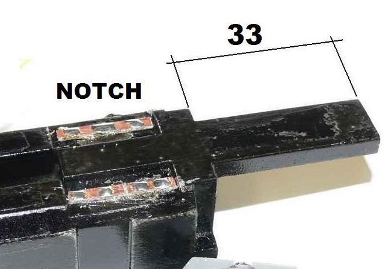
The decoder MUST be mounted at the rear of the locomotive so make sure you drill and CUT the right ends, refer location of the notch this is the front of the engine weight.
Note Optional:
Fit two pieces of PCB, trim to size and glue into the position shown in the photo, this is in the recess in the weight.Select one and tin at three points, next cut thru the top layer of the PCB about its centre line, this forms two separate solder pads, apply two points of solder on each pad, these will be used later to collect up the lights
 Drill a 1.5 mm hole thru the top feed wires thru and test fit speaker and thread wires thru 1.5 mm hole.Test fit the speaker to the casting, clean any moulding imperfections with a single edge modellers blade using a scraping action. Urethane is very soft and will remove quickly so exercise a little patience.
Apply a thin a bead of sealant refer area A into the recess and then fit speaker. Next seal opening were the wires exit and the notch in the base at point C, set aside and allow to dry. The base may need a sand to remove the taper created in the casting process, work slowly with a guide utill flat.
 |
| Mount Decoder on underside of rear tongue and thread wires through as shown |
Remove the wire soldered to the slip on the metal clip on the topside of the motor as we will not need this. The lower side of the motor has two wires connected to the motor, we cut one of the [blue wire in photo] flush with the point is fixed to the motor. Next we connect the front and rear trucks with a new feeder in black and red. Red is on the right hand side looking from the rear of the locomotive forward.
 |
| Decoder mounting |

Finally place a solder point on the top side of the metal strip located on the topside of the motor.
Next install the decoder, cut off the NMRA 8 pin plug and thread the wires thru the hole we drilled in the chassis.
Cover the mounting face with a layer of electrical tape and then install the decoder on its flattest face threading the wire thru the hole provided, fix decoder with a loop of electrical tape as shown in the photo's opposite.
Now begin to connect the decoder onto the solder points provided on our modified frame. Loop the red and black decoder wires to their respective trucks [refer photo's]. Thread the wire from the bottom motor connection thru slot on frame.
Connect the motor, solder the grey lead to the solder point on the strip located on the top of the motor, connect he orange wire from the decoder to the wire from the bottom of the motor, solder together, insulate with liquid insulation or heat shrink.
The light connections are now added, blue to the common copper strip with the three points of solder and the yellow and white to one of the split pads.

The lights will consist of two lights, trim to length and solder one leg to the solder point on the common blue decoder wire solder pad and the other to the split pad, one pad is used for the white decoder wire for the front headlight and the other for the yellow decoder wire for the rear headlight.
Cover the lights with a length of black electrical tape to seal the lights at both ends [front shown without cover for clarity]


Crew points are provided but they will require cutting along the body line to fit the recess provided but this is not noticed from the outside.
One you are sure everything is running refit body and you are ready for the track.
Note: you will not hear the decoder fully until the body is installed.
Subscribe to:
Posts (Atom)