Thursday, 23 November 2023

Powerline T Class

This blog cover the installation of sound into the Powerline T class and a SoundTraxx Econami - intermediate level

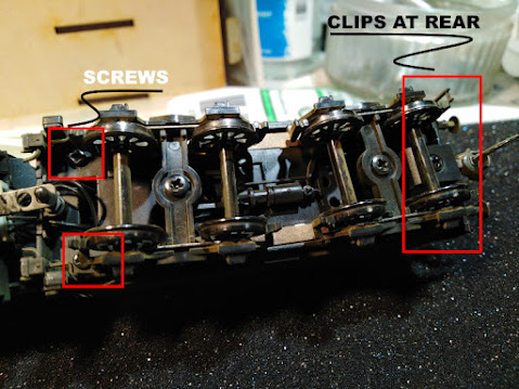
The shell is secured using four [4] self tapping screws located on the underside of the locomotive at each end. These are very short and may not grip on reinstallation, so be careful when tightening. Next, remove both coupler and pockets. We recommend the couplers be replaced, they are a low quality copy of the Kadee, whisker type recommended.

The board used is a standard Atlas DA-SR type and secured with the clips inserted through the decoder. Photo graph all the wiring before proceeding.

Both the markers are wired to the front and rear headlights alternatively and we will split these at installation. The wiring colours are all over the place so just identify each one removed which is done by sliding back the plastic clips and removing the wire. Once done arrange so you know who is who especially the track pickups.

Extend the motor wires by about 30 mm for reinstallation.

Locate the front of the decoder as per the diagram supplied with the decoder after tinning all the front and rear lugs along with the speakers and FX3/4.

Remove the mounting clip using the two screws into the chassis and relocate so the wire retainers are just over the rear edge of the current mounting location. Secure using ACC or Kaptron tape.


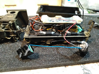
Mounting clip and speaker refitted


Next solder the speakers wires onto the speaker allowing about 60 mm for trimming at installation. Secure the speaker in its location in the pocket at the rear of the chassis near the rear lighting.

Buzz the track wire to confirm which ones are the track wires, there are NO mistakes here.

Solder all the wires to there respective lugs including the front and rear markers FX3/4 - Front/ Rear markers. Note how on the rear wiring the unused mounting holes are used to keep the wires in place for reassembly


Check you have 8 ohms across the speaker attachment points after soldering the wires.

Place your locomotive and connect the PowerCab to one track after setting it to display to amps. Tap the other wire on the track and if the current runs past 0.04 amps STOP there is something wrong. 

With the Soundtraxx Econami decoder shown a blue status light will shown that all is OK. Configure the decoder to your personal taste, we used JMRI as most sound decoders are well beyond hand programming.

Test is all is OK reinstall the shell in the reverse order. We found it harder to install than remove and dressed both end to remove every burr and finally it slipped back but I cannot confirm why.

With tuning it will run smoothy but mak

Ensure the wheels are polished as this locomotive could do with a small stay alive but there is barely any room for the speaker as it is. We polish the wheels by liberally applying WD40 to the track and wheels and allow the loco to run at speed step 3-4 against a fixed stop across the track. When done thoroughly clean the wheels with WD40 using a cotton bud.


Wednesday, 19 April 2023

NCE Dual Relays

NCE produced the Dual relay to allow both the Switch-it and the Switch 8 to operate as a digital switch using the Dual relay.

The reason is solid-state transistor switch on the decoders can only handle about 40 ma, which is more than enough for a typical; Tortoise motor but is limited to that. The Dual Relay was created to handle up to 2 amps to allow the decoder to switch a relay. To achieve this, the relay coils had to have high resistance to limit the current within both decoder specifications.

There is an error in the nomenclature printed on the decoders. It's all back to front, and if wired as shown, it will not operate, or the wrong outputs will operate.

I have created a correct corrected image that will operate as specified when wired as shown will operate to specification..


Wednesday, 1 March 2023

Bendigo Models T Class

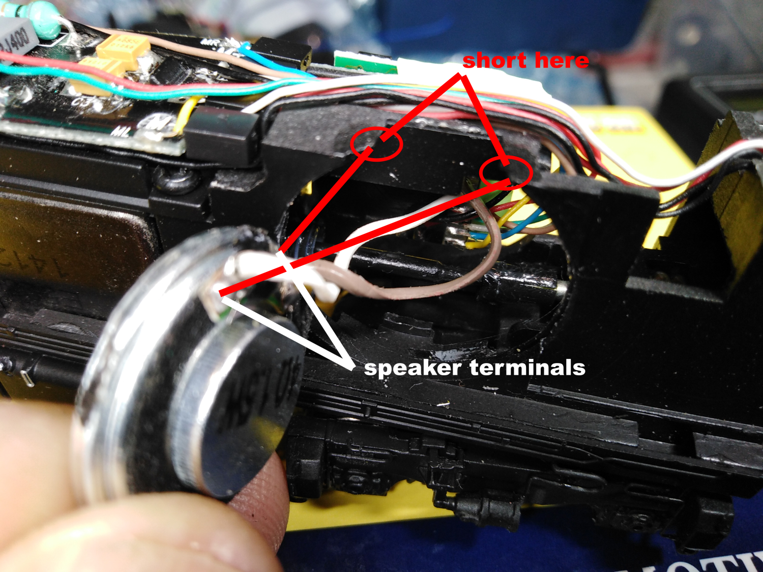
The ESU V5 sound decoders cannot have the audio shorted at any point when power from the track is applied. Most of the files we supply are tidied-up files from ESU and are tested before dispatch, that is, they are run in a decoder tester with a large speaker, so we know they work at dispatch.

A customer returned this locomotive with the decoder and speaker installed, as we could not diagnose the issue over the phone. The customer retested the locomotive with the DC plug, which ruled out a locomotive issue as the engine ran smoothly.


When tested in the ESU programmer, the decoder returned
"Decoder not recognized" regardless of the method applied. We then realised that the speaker had been installed in reverse, which shorted the speaker terminals across the chassis at the top edge.


As shown, the speaker mount was designed to have the speaker face into the chassis; a final trick to get the best volume is to apply a piece of brown packaging tape across the back before reinstallation. This seals the enclosure in a superior manner to the locomotive wall and will increase speaker fidelity in operation.


I chose to seal the gap between the rim of the speaker and the frame using liquid insulation available at Jaycar. It is expensive and prone to drying up, so as you use it, wind up the used portion of the tube at all times, fit the cap and store it nose down. Now does it make a great difference, hard to say, but it will cannot hurt.

Note: The ESU 23 mm 4-ohm speaker is the only one that will fit this application. Our micro-speaker is a good substitute if not available.

As the engine and decoder were supplied by the MRRC, this cost $75 for a new decoder repair and installation.


Correct installation and remember the packaging tape
across the back of the speaker


Saturday, 21 January 2023

NMRA 8 pin plugs

This is a small warning about using the DC shorting strips supplied with any DCC-comparable engine.

These are NOT an 8-pin plug as they have shorting strips connecting the motor and lights directly to the track, and if used without removing ALL these connections, it will destroy your decoder.


An 8-pin plug is just that, 8-pins with NO connections. I strip all the wires on the decoder about 4 mm, and then all the wires are tinned with the iron tip at about 325 deg C to reduce the pullback of the PVC insulation.

Apply a small amount of solder onto the tip, then touch the tip to the wire end, and finally touch the 60-40 resin solder, allowing the solder to flow up the bare wire. Finally, trim the soldered end to about 1 to 1.5 mm.

Fit the plug into any 8-pin socket, I use my decoder tester for this task. This prevents the plug from damaging itself when the wires are added. If it is, an 8-pin IC socket fill the holes with solder before attempting to attach any wires. A PCB wire type has a pool of solder as part of its assembly.

Start with the orange, complete the lower and then the upper row. Check against the diagram the check again...!

NMRA 8 pin wiring pattern


Tuesday, 4 October 2022

JMRI & the PowerCab

One of the major reasons a modeller will invest in the NCE USB interface is the need to use JMRI. This is understandable as most decoders are beyond hand programming in the areas of functions mapping, speed curves not to mention sound.

One of the major issues is getting it to work on the laptop/PC. Firstly the USB interface will work correctly when windows get into sink with the NCE hardware.

Step 1

You must download the Silicon Labs driver, it is the only one that will work.

Step 2

You have to get windows to use it. If you have used any device that requires a UHART driver, windows will go out on the web [if online] and use anyone available, but most likely not the Silicon Labs Driver.

Step 3

Check your driver as shown below by right-clicking on the windows icon, then clicking on the device manager tab and opening the ports tab. You must use the Silicon Labs Driver listed if not there, delete the offending one and then install the silicon labs driver.

https://www.silabs.com/developers/usb-to-uart-bridge-vcp-drivers?tab=downloads

Type: Windows Drivers

Step 4

All the drivers are installed on demand, so check that there is no driver, then plug in the NCE USB when coupled to the PowerCab. The driver will load - repeat the process we started with to check that the Silicon Labs driver has been installed.


Click to enlarge


Tuesday, 5 October 2021

QSI 50 Class Stay Alive

A Eureka 50 Class will run well out of the box but we have found the addition of a stay alive will improve its running significantly.

All steam engines suffer from pickup issues much more than say a diesel locomotive, this is due to their long rigid wheelbase making tender pickup a necessity so where possible a stay alive is a must-have accessory.

Fortunately, the QSI decoder in the NSWGR Eureka 50 class has a capacitor for DC operation making the task fairly straightforward.

Begin by removing the two self tappers at the front and by sliding back and inserting a single edge blade at the rear lever the back end away.

Note: remember to disconnect the ladder from the tender deck using fine tweezers.


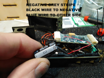
With the top in a safe place locate the factory capacitor at the front of the tender, remove and using a blade expose the wire by removing a small amount of the heat shrink. On this locomotive, the positive was red and the negative black but the grey stripe on the capacitor is always denoting the capacitors negative.


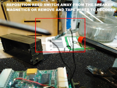
The next task was to remove the reed switch which is why this was pulled apart to start. If the reed switch falls under the influence of the speaker magnetics it will always be resetting and not allowing the locomotive to operate as intended.


With the stay alive installed it is time to reassemble the tender.

Test run the locomotive as shown on the linked video before closing the tender for a final test.

Place the stay alive across the tender under the decoder with the smooth side up. Reinstall the factory capacitor at the front in its original location and start to close up

This is a rats nest so a little jiggle is required but it will close.

Insert the lug into their slots at the rear, slide back to engage the tender body at the rear, then reinsert the two [2] self tappers at the front of the tender.

If it does not close repack and try again


There are separate blogs on setting the long address and undertaking a reset of the decoder on a programming track which will have to be done after removing the reed switch.

To view video showing operation with the stay alive installed on Rumble: Click here


Tuesday, 5 May 2020

Function Only

SDS models have created an unpowered model of the NR Class featuring a 21 pin DCC board to allow installation of a function only decoder. We will look at using a cheap LasicDCC 21 decoder as a function only.
.
Most function only decoders are as expensive as the same decoder for a powered engine and provide limited functionality. The issue lays in the fact that even though it may be possible to blind program a decoder, it is nice to have a readback for the CV's

Using the NR as an example, we can install a 22 ohm 1/4 watt resistor across the motor inputs to simulated the required load for a decoder to program correctly. The only issue is of course as we run up the steps the power delivery defined by the speed curve will create overheating.

The simplest way to remove this issue is to use the three basic CV's to set CV2,6,5 at a value of 1 to achieve a low potential difference across the resistor and thus limit the total power demand and therefore heat. 


The orange line represents a typical power curve for a powered engine while the red line represents a restricted power curve for the
non-powered decoder


Tuesday, 25 February 2020

Coffee Pot

This is an intermediate skill installation with some function splitting.

The roof of the passenger carriage is removed using a fin X-Acto blade - it is retained by four [4] moulded in clips.


With the roof removed the factory-installed wiring and boards are exposed.

With this installation, two [2] speakers were installed. One a 0.75'' round was installed in the provided location under the passenger carriage covered by a black casting with some small holes.


The second was an ESU 16 x 25 installed under the cab roof, combined these gave a good spread of sound removing the possibility of the engine being perceived as being under the carriage.

There was two brown projection that had to be removed to allow the floor-mounted speaker to be fitted and these were removed with a pair of angled Xuron nippers.


Both speakers were wired in parallel and providing a final resistance of 12 ohms which is fins with the sound decoders selected.

The selected decoder was a Soundtraxx Econami UK with the whistle and chuff left on defaults and auto brake, cylinder cocks activated. The air compressor was activated, but not a dynamo for the headlight as these would have been an oil lamp or similar.

The lights used for these was a low brightness for the headlight and passenger carriage. Firebox flicker was used for the firebox and another low-intensity light for the passenger compartment.

An eight [8] pin plug was soldered to the wires supplied with the decoder and then a series of solder pads fixed with contact cement to allow the functions to be split up. 

FireBox
A red LasicDCC LED light was fixed to the weight in the cab with the LED closest to the floor. These are complete and ready to use, so no resistors just connect to the green wire - FX3. This has the flickering firebox effect added.

Passenger Car Lights
The factory lights were reused but separated into FX4 to allow operator operation to separate it from the headlight.


Note location of orange wire.

Install solder pad into the corner shown then collect all the blue wires from the two compartments and vestibule onto that pad and then fit brown wire from FX4 - this places this output in control of the lights.

Positives/Stay Alive
All the positives for the lights were collected as shown and a single wire runs from the blue on the eight [8] pin plug to the pad.

A stay alive was installed to ensure smooth operation due to the limited pickup of this engine, in-fact all steam engines should have these fitted.


Overall it worked well


Monday, 9 December 2019

44 Class

This blog covers the installation of an ESU decoder into the Train-o-Rama 44 class. The speaker used is a 1'' diameter QSI, but there is now an alternative to suit the factory speakers. 

Begin by removing both staff exchangers, this is done by simply sliding a screwdriver or similar under the side of the shell and extracting both staff exchangers, remove the couplers and then slip off the body. 

Note: the rear headlights are attached to the light board with two wires

Next, remove both speakers supplied by the manufacturer. Start by removing the black plastic lugs unscrew the retaining screw of the light board just enough to gain better access for the install. 

Place the lugs, screws, gaskets, and covers to one side. 

Next, remove the rear fan and cover. This is done by simply drilling the grey lug retaining the cap. Using a 2.0 mm drill or similar just spin with your finger till the grey lug is removed to the lid. 


Lever the cap away and store, we will not be reinstalling it. 

Cut both cables, install the brown speaker wire onto the lugs for the rear speaker as shown.  Drill a 1.5 mm hole thru the speaker and pass-thru wires, seal the speaker into the enclosure using PVA. Repeat where the cables exit the ring but do not get glue onto the speaker during this process. 


To fit the speaker to the existing cutout, apply a little contact adhesive to the edge of the enclosure and while wet fit to the enclosure to transfer a bit of the contact adhesive. Allow to tack off and then fit the speaker as shown opposite. 

Connect speaker wires at point A-B, and there is no specific order, then decoder speaker wires at the rear as shown.


Trim excess heat shrink at the rear of decoder this will ensure a better fit, best done with a sharp blade. The rear wall can also be removed to improve the available space is another decoder is used as it does not affect the final appearance.

Re-install the original factory speaker retainer as shown.


Retighten light board screws only after all wires and lugs are refitted. Now tape the decoder into position and plug into the 8 pin socket provided. 


The locomotive has 12 pin socket, make sure the plug is installed into the correct part of the socket [refer photo]. Fit jumper provided, note jumper wires must run across the locomotive. 

Note: This jumper links the front speaker to the decoder via the factory-supplied PCB

Place locomotive on the track and hit the assigned start button, your 44 will now spring into life. Once satisfied refit body, staff exchangers and couplers, set the locomotive address and its ready for service.


Tuesday, 28 May 2019

30 Class Tank Lighted

The Auscision 30 Class is also supplied in a lighted version and is tighter that the non lighted model blogged previously.tank has no real space for a sound decoder and thus has to be installed in the cab area. This conversion dose require use of small hand tools to complete the necessary modifications


Begin by removing the cab roof, this is clipped in at the front and rear and can be removed 
using a small blade screw driver, next separate the bunker extension located on the top of the coal bunker, these are mounted by a small moulded lug into the all metal coal bunker. 

To remove the coal bunker locate the two screws securing the bunker on the underside of the footplate, these are be removed with a small Phillips head screwdriver. Do not remove the screws under the side bunker

See photos for clarity, place the screws and bunker to one side.


With the parts separated modify the cab rear and bunker extension as shown below. A fine razor saw and file are required to complete this task. Remove the glazing before modifying the cab then mark the glazing from the cab and modify as required then reinstall with a small dot of contact cement.


CAB MODIFICATION - numbers are in mm
Note clips that secure the cab


BUNKER EXTENSION MODIFICATION - numbers are in mm

The decoder loom is to long and we chose reduced the overall length to 30 mm - speaker wire should be 35 mm. 


Note: The MRRC will modify this with a charge at time of ordering. The location of the #1 pin [Orange wire] means that when soldering the wires to the plug that this be accommodated - see diagram opposite.

This is required to allow plug to be installed into the socket


The installation of the SoundTraxx Econami UK creates a number of issues over a ESU in that a capacitor is required and requires a edge port speaker to prevent crowding the cab area. The speaker used has a 6 ohm impedance and if the master volume and in particular the whistle a kept at about 2/3 maximum volume this will be OK.

The capacitor was fixed in the mouth of the firebox door and painted black after marking the negative [grey stripe] clearly. Glue with a dot of contact on the base ,set aside to dry.


Comment
Refer to blog on installing a ESU decoder into a non lighted 30 Class for additional information

Tuesday, 23 April 2019

Ixion 32 Class

This blog cove the installation of a Soundtraxx Tsunami with stay alive into the Ixion Class

Installation
This could be described as a relatively easy installation

Remove the tender, this is secured by three [3] clips located along both sides of the tender floor. The best method is to insert a single edge blade in the gap between the shell and floor and lever open the tender from both sides.

One removed to disconnect the plug to the rear marker lights and place the shell to one side

The installation required the addition of an 8 pin plug wired the NMRA standards and trimming the loom to about 30 mm long. 

Do not cut the yellow-green wire of the purple speaker wires.


Next, remove the factory speaker mount and trim off all the lugs. 

Dress the underside if the factory supplied board and fix to the tender floor using a cardboard insulator and contact cement - this is outlined in the instructions for the Wombat  30T.

Install to the image below, the speaker is fixed at the rear using contact cement leaving enough room for the Lasic small stay alive. This as also secured with a drop of contact cement thought blue tack would work

The decoder is installed on its side in a bed of blue tack.


To allow the shell to be re-fitted the internal weight need to be relocated into the coal bunker. The first task is to remove the lower lip on the underside to allow a neat coal load to be formed. The weight is glued providing an opening all the way around three [3] side again for the coal load.


Material Required

Soundtraxx TSU1000 Tusanimi 2 custom programmed by MRRC

MRRC Micro Boost Large

Lasic Small Stay Alive

Wednesday, 6 February 2019

HMA Crossing Gates

This blog covers the use of an NCE Light-It to operate the LED's on an HMA Crossing Gate #2407.

Installation
The positive [5 VDC] from the Light_it was connected to the red positive of the HMA Flashers which are arranged in pairs left/right-ha side.

The decoder was connected for testing on its loco address of #3 and using programming on the main [POM] the relevant CV's 137/138 were set to effect 9 for a Phase A.


The user has a choice of DC / DCC for operation and in DCC can use a loco or accessory address. When using an accessory address, additionally have the option of syncing the flasher lights using a combination of option 9 / 10.

The simplest way to operate these would be to use DC and a BOD20 or other device to apply the power across the Light-It connection.  This project is for a customer and will feature full flashing lights/gate operation and sound controlled using an NCE Mini Panel.


Wednesday, 12 December 2018

Lima XPT

Thought these are now getting old the XPT is still popular as it offers a cheap Australian look alike.

Installation
It was decided to install a Lasic decoder with stay alive as they are a good cost match to the locomotive. The installation is straightforward as the motor pickup is clearly located on the motor.

Begin by removing all the existing wiring for the motor and lights as these will be upgraded to LED as part of this conversion.

DCC is very sensitive to pick-up and the basic pickup originally supplied with these locomotives has to be improved, this is done in two ways, firstly the front bogie is rewired and upgraded and secondly a stay alive was added.


Fixing locomotive weight

Modification to front bogie consist of hardwiring to the factory pickup

Lower clip is released and the working face cleaned and tinned, a feeder wire was soldered  and a hole drilled to allow it to pass through the bogie frame 

Note: ensure that the exit point does not foul on the pickup of the assembly

A hole is drilled through the frame to allow connection to the tab, next the tab was fixed over the pin by pushing it over the pin and then lifting the pin to engage in a groove located on the pin.

Decoder installation - the grey & orange arranged as shown allowed
fwd to operate correctly

Decoder and Stay Alive Installation

In the image above note the heat shrink, this contains a pin/socket that allows the stay alive to be disconnected for programming - this proved to be an issue with this decoder.


LED headlight

A LED installed replacing the rather clunky headlight original installed. To do this the cover was removed from the chassis and a LED module incorporating the LED and resistors, it was fixed with contact cement to the locomotive cover and once dry the refitted to the chassis.


Cutout to clear decoder

At assembly, the perspex fouled the decoder but a quick trim allowed a neat fit and finally the hood to be reinstalled.

With a small amount of adjustment and clean wheels, it moved off with as much grace as these units are capable of.

All items used in the installation are available from the MRRC.